Location:Home > APPLICATION
Selection of Process Parameters for Ultrasonic Phased Array Inspection of Welds
Release time:2023-09-26
At present, traditional ultrasonic and X-ray inspection methods are still mostly used in the inspection of ship construction in China. Although these technologies are relatively mature, they take a long time and the process is relatively complex. In addition, ionizing radiation from radiation poses a certain degree of harm to the human body, and after the hull is closed, some welding seams need to shorten the focal length of the film due to limited space, which can lead to a decrease in the quality of the film and affect the detection rate of defects.
In contrast, the ultrasonic phased array detection method is convenient, flexible, non radiative, and does not affect surrounding construction. It can detect materials with large wall thickness, and does not require opening or sealing holes when encountering structures. It can be operated on one side at the work site and can locate the depth of defects, making repair convenient. This can effectively reduce detection costs and accelerate construction progress.
Meanwhile, when using the ultrasonic phased array detection method for detection, the detection results can be obtained by simply connecting the detection equipment to the computer, which is more timely and efficient. However, selecting the correct detection parameters before the start of testing is the foundation for successful use of ultrasonic phased array testing, otherwise there may be phenomena such as missed detection and misjudgment, which will bring inconvenience to quality and construction.
Meanwhile, when using the ultrasonic phased array detection method for detection, the detection results can be obtained by simply connecting the detection equipment to the computer, which is more timely and efficient. However, selecting the correct detection parameters before the start of testing is the foundation for successful use of ultrasonic phased array testing, otherwise there may be phenomena such as missed detection and misjudgment, which will bring inconvenience to quality and construction.
Ultrasonic phased array detection system
Selection of components
Selection of components
The ultrasonic phased array detection system mainly includes hardware composed of a flaw detector, probes, wedges, etc., as well as software part of the focusing law composed of excitation chips, focusing range, scanning angle range, angle stepping, etc. The selection of detection system parameters mainly refers to the selection of hardware and software system parameters. Correct selection of their parameters is crucial for effectively detecting defects and for defect localization, quantification, and even qualitative analysis. In actual detection, the selection should be based on the structural shape, size, processing technology, and technical requirements of the inspected workpiece.
﹃ Selection of instruments﹄
At present, there are many brands of phased array instruments both domestically and internationally, and different instruments have their own characteristics. Therefore, the selection of testing instruments should be based on testing requirements and on-site conditions.
(1) Instruments with better horizontal linearity and amplitude linearity should be selected to more accurately locate and quantify defects. The measurement method and maximum error requirements can refer to the standard ASTM SE-2491.
(2) The actual engineering testing application environment is mostly in the workshop or outdoors, and it is advisable to choose instruments that are lightweight, portable, have good screen brightness, and have a simple operating system.
(3) The ultrasonic phased array system has a series of transmitters and receivers, and their number is usually a multiple of 16, which is a limit imposed by the instrument on the maximum number of excitation probe chips by a set of focusing laws. For example, for a 32/128 phased array system, there are 32 channel transmitters and 32 channel receivers, and it is possible to switch to probes that support 128 channels. However, in a single focusing law, the maximum number of chips excited at any one time is 32. For unused channels, they can be used for certain detection of single crystal probes, such as the detection of a pair of TOFD probes.
﹃Selection of probes and wedges﹄
At present, there are many brands of phased array instruments both domestically and internationally, and different instruments have their own characteristics. Therefore, the selection of testing instruments should be based on testing requirements and on-site conditions.
(1) Instruments with better horizontal linearity and amplitude linearity should be selected to more accurately locate and quantify defects. The measurement method and maximum error requirements can refer to the standard ASTM SE-2491.
(2) The actual engineering testing application environment is mostly in the workshop or outdoors, and it is advisable to choose instruments that are lightweight, portable, have good screen brightness, and have a simple operating system.
(3) The ultrasonic phased array system has a series of transmitters and receivers, and their number is usually a multiple of 16, which is a limit imposed by the instrument on the maximum number of excitation probe chips by a set of focusing laws. For example, for a 32/128 phased array system, there are 32 channel transmitters and 32 channel receivers, and it is possible to switch to probes that support 128 channels. However, in a single focusing law, the maximum number of chips excited at any one time is 32. For unused channels, they can be used for certain detection of single crystal probes, such as the detection of a pair of TOFD probes.
Ultrasonic phased array detection
process parameters
process parameters
The parameters of the acoustic beam excited by a phased array system need to comprehensively consider multiple factors. The scanning method of the acoustic beam, the number and position of the excited chips, the acoustic beam waveform, probe offset, acoustic beam angle, and focusing range all affect the detection results. The selection of process parameters should follow the following basic principles:
(1) The sound beam can cover all the volume, heat affected zone, and 6mm outside the inspected weld seam.
(2) After the set parameters have been calibrated by the instrument, they should be successfully certified on the certification test block.
(3) Other requirements that comply with standard specifications.
﹃Sound beam scanning method﹄
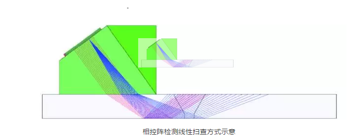
In weld seam inspection, sector scanning (S-scan) is usually used, but in some special cases, linear scanning (E-scan) can be used to detect defects in a specific area. For example, for incomplete fusion defects in the groove, setting a set of linear scans perpendicular to the groove is very effective (see the figure below). The blue sector scan is used to cover the inside, root, and heat affected zone of the weld, while the red line scan is specifically set for the groove area. But for most standards, this is not a mandatory requirement.
﹃声束类型﹄
在检测焊缝时,通常采用横波声束以及一次反射法来扫查焊缝,但对于晶粒相对粗大的不锈钢焊缝,有时即使采用低频的横波,依然存在着衰减严重、信噪比差的情况。此时,采用纵波角度入射不失为一种好的解决方法,如某公司为检测不锈钢而设计开发的DMA探头,就是利用纵波一发一收的原理。
﹃Sound beam angle range﹄
The selection of sound beam angle range should comprehensively consider the selected wedge and weld size. Any wedge has its center angle, and the selected angle range should be within the recommended value range of the wedge manufacturer to ensure the reliability and controllability of the sound beam. The smaller the angle range of the sound beam, the more limited the volume of the covered weld seam. This group of sound beams may not fully cover the inspected area, so it is recommended to choose a large range of sound beams within the range recommended by the manufacturer. However, for the detection of large wall thickness welds or other situations, when a set of sound beams is set to the maximum range and still cannot effectively cover the inspected area, one or more sets of sound beams should be added.
﹃Probe offset and chip excitation starting position﹄
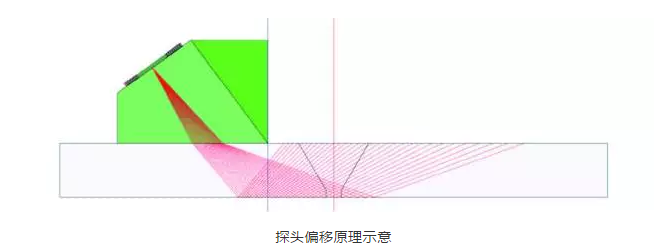
Probe offset generally refers to the distance from the center of the weld seam to the front edge of the probe, which, along with the starting position of the chip excitation, affects the relative position of the probe, sound beam, and weld seam. In the presence of excess height in the weld seam, sufficient probe offset should be ensured to avoid the probe leading edge pressing on the weld seam excess height and causing coupling failure. Usually, under the premise of ensuring coverage of the inspected area, the probe offset is adjusted so that the activated chip is in the middle position of the probe (see figure below).
﹃Number of excitation chips﹄
The more excited the number of chips, the larger the size of the effective chip, the greater the energy radiated by ultrasonic waves, and the stronger the ability to detect distant defects. At the same time, the near-field region also increases with the increase of chip size, which has a wide range of focus and is beneficial for detection. But too many excitation chips also pose higher requirements for phased array systems. If 32 chips need to be excited, 16/128 devices cannot be implemented, and at least 32/128 devices need to be used; In addition, increasing the number of excitation chips will affect the scanning speed and also increase the burden of data storage. It is recommended to excite 16 chips for general material testing, and for materials with thick walls or slightly larger sound attenuation coefficients, the number of chips can be appropriately increased.
﹃focus range﹄
Unlike conventional ultrasound, ultrasonic phased array systems can achieve dynamic focusing of sound beams. As is well known, in the focusing area, the more concentrated the energy of sound waves, the higher the sensitivity and resolution. Therefore, it is particularly important to set the focusing area correctly. For relatively small weld seams, the focus area can be set in the middle of the weld seam, but as the wall thickness increases, the weld seam can be divided into several areas and detected using different sound beam focuses. In addition, if you want to accurately detect defects in a certain area, you can set the focus on that area.
Process parameters
Select Instance
Select Instance
A phased array inspection was conducted on the pipeline butt weld during the construction process of a certain LNG (liquefied natural gas) platform. The tested material was A333 steel (low-temperature carbon steel), the welding process was argon arc welding, the groove form was "V", the pipe diameter was 200 mm, and the wall thickness was 12.7 mm. The detection equipment used is OMNISCAN MX1 or MX2, with a probe model of 5L32-A11 and a wedge model of SA11-N55S-AOD8.625. The parameter selection for the phased array system and probe is as follows:
﹃sector scan﹄
Beam type: transverse wave
Probe offset: 16 mm
Number of excited chips: 16 (9-25)
Beam angle: 40 °~70 °
Focusing position: 19 mm
Probe offset: 16 mm
Number of excited chips: 16 (9-25)
Beam angle: 40 °~70 °
Focusing position: 19 mm
﹃Line scanning﹄
Beam type: transverse wave
Probe offset: 22 mm
Number of excitation chips: 8
Beam angle: 60 °
Focusing position: 19 mmDuring testing, a maximum of 16 chips can be excited at once. The ultrasonic phased array device should have at least 16 channels, with MX1 being 16/128 and MX2 being 32/128. The tested material is ordinary carbon steel, which is not a high attenuation coefficient material. To obtain better sensitivity and resolution, a 5 MHz probe can be selected; At the same time, the A11 probe is smaller than the A12 probe, which provides better coupling effect for pipelines with a diameter of 200 mm. The wedge matched to the A11 probe is the SA11 series. According to process simulation, transverse wave detection is used, that is, a transverse wave wedge with a center angle of 55 ° is used. At the same time, to achieve better coupling effect, the wedge should have a curvature close to the workpiece being tested (the diameter of the wedge should be slightly larger than the workpiece being tested, otherwise the center of the wedge cannot be in close contact with the workpiece).
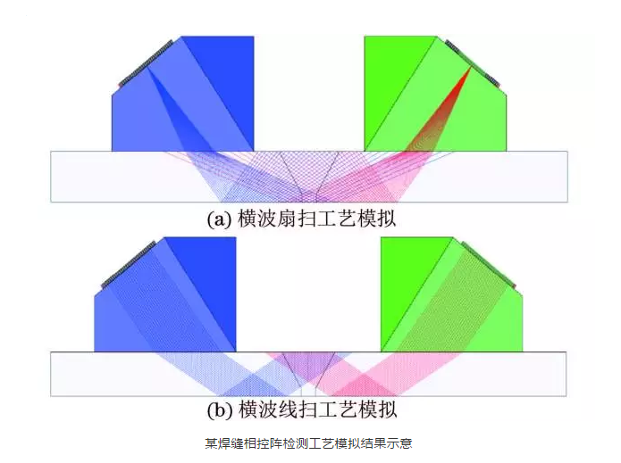
The wall thickness and volume of the inspected weld seam are relatively small, and using a set of fan scans can effectively cover the inspected volume. At the same time, for high-risk incomplete fusion defects in the groove, a line scan perpendicular to the groove is used to assist. The beam type uses the transverse wave reflection method. If the surface width of the inspected weld seam is 18 mm, the probe offset should be at least 9 mm. The beam range of the fan scan covers the weld seam and its heat affected zone, and is also within the manufacturer's recommended range. The focus range is set at the center of the weld seam.
The probe offset, excitation chip, and beam range are all determined by the inspected weld seam itself, but they are not absolute fixed values. These values can be simulated, modified, and confirmed through acoustic beam simulation software. The simulation results of the process are shown in the following figure.
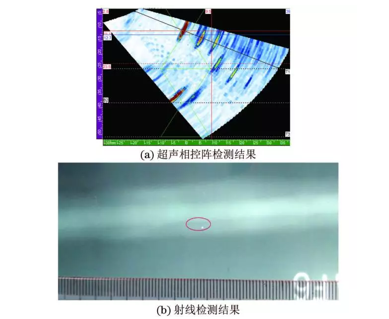
Using this process for weld inspection, after scanning and analyzing the data, a root defect with a length of 7 mm was found. Special radiographic testing was conducted on this weld seam, and the results are consistent with those of ultrasonic phased array testing.
Conclusion
The ultrasonic phased array detection system has obvious advantages, but its system is slightly more complex compared to traditional ultrasonic detection. When formulating its detection process, various factors should be comprehensively considered, and its detection effect must be verified through experiments. If adverse factors such as missed detection and poor signal-to-noise ratio are found during the testing process, the process parameters should be adjusted.