MWS-6 manual ultrasonic vane scanner
–Semi-automated inspection of composite materials
The MWS-6 is a manual linear scanner specifically designed for in-service wind turbine blade inspection, which is easy to operate and easy to archive and store inspection results, giving wind farm owners and operators the flexibility to randomly inspect installed blades.
MWS-6 description
• Manual linear scanner for composite structures
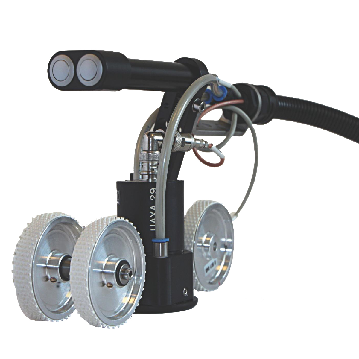
• The scanner body has a single probe holder and an encoder wheel
• Two operating control buttons with programmable functions,
• Scanning mechanical accessories allow scanning with blade contour edges
Functional characteristics
On site testing of wind turbine blades
MWS-6 will simplify your inspection process. It is a manually operated scanner mainly used for semi-automatic detection of composite materials. This scanner is an ideal portable solution for random on-site detection of vertical blades.
High performance ultrasonic sensors provide you with the most superior performance and reliable data, which can be used in your inspection and repair processes.
These data include information about the areas you need to repair and their accurate locations, which makes your repair area even more limited.
The MWS-6 is easy to operate on an upright working platform along the installed wind turbine blades, and the scanning rack is an ideal full size supplementary scanning device that can pre identify and detect new areas or re inspect known areas of concern.
host interface
WS-6 can be connected to any version of the system for use, with a unique design that emphasizes fast time setting, lightweight and easy to use, thereby improving usage efficiency.
In addition, the system has great flexibility and can adapt to different testing scenarios, covering most of the main ultrasonic testing technologies.
Able to adapt to different line scanning situations
The scanner adopts an aluminum mounting rod, probe bracket, handle, support wheel, encoder wheel, and special accessories installed on it. This design configures the scanner component into three different linear array scanning scenarios:
• Line scanning parallel to edges
• Line scan perpendicular to the edge
• Line scanning is independent of edges on a plane
The scanner cable is connected to the P-scan processor through two electronic modules of UT signal, encoder, and switch signal
Scanner Configuration
The scanner component can be placed on the installation rod to facilitate different scanning applications. The probe bracket and encoder wheel are installed "side by side" for scanning relative to the edge and other application scenarios.
Scanning parallel to the edge
This application uses a "side by side" installation of coding wheels and probe brackets. Two guide rods are fixed on the installation rod, and the rollers on the guide rods are pushed into place. Using this setting, the maximum scanning distance from the edge is approximately 340 millimeters.
Line scan to edge
This application uses a "side by side" installation of encoding wheels, probe brackets, and support rollers. To directly scan the edges, it is necessary to install the encoder wheel on the opposite side of the probe housing and align it with the center of the probe.
Line scan independent of edges
This application uses an "online" installation of encoder wheels and probe brackets. The support wheel group is installed in front of the probe, and the coding wheel is installed behind the probe.
Technical Parameter
|
Encoder resolution |
2000p/r |
|
Resolution |
3mm |
|
Height x width x length |
84x217x161mm |
|
Dust and waterproof |
IP 54 |
|
operation temperature |
0 -50 ℃ |