Analysis of Near Field and Blind Areas in Ultrasonic Testing
1. The near-field zone is mainly caused by the interference of sound waves near the wave source, while the blind zone is mainly caused by the characteristics of the instrument's emitted pulses and the performance of the amplifier.
2. The ultrasonic pressure in the near field area is irregular, and the quantification of defect echoes is not accurate; Blind spots are areas where the defect echo signal cannot be amplified and displayed.
3. The length of the near field is calculated, and the size of the blind spot is measured through testing.
1、 Near field region
1. Near field concept:
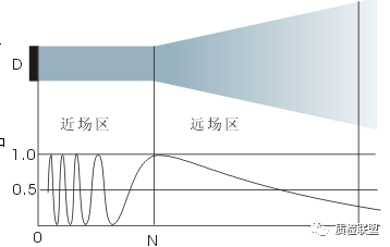
The near-field region, also known as the Fresnel region, is an area where a series of maximum and minimum sound pressure values appear near the wave source due to wave interference. The distance from the last maximum sound pressure on the axis of the wave source to the wave source is called the near-field length. The presence of near field areas can lead to inaccurate quantification of defect echoes.
2、Calculation formula for near field region:
The formula for the near-field length of longitudinal waves in a circular source:
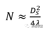
(Where Ds is the diameter of the disk source, λ Is the wavelength)
The formula for the near-field length of longitudinal waves in rectangular sources:
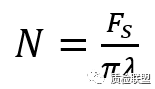
(Where Fs is the area of the rectangular source, λ Is the wavelength)
3、Factors affecting the near field region:
The larger the area Fs of the sound source, the greater the near-field length N;
The higher the frequency f, the longer the wavelength λ The smaller the distance, the larger the near field length N
二、blind area
1、The concept of blind spots:
The emission pulse of the emission circuit of the ultrasound instrument excites the probe and directly enters the receiving circuit, forming a starting wave. Due to the high emission pulse voltage, the amplification factor of the amplifier will decrease or even have no amplification effect in a short period of time, which becomes a blockage. Due to the inherent width of the transmitting pulse and the blocking phenomenon of the amplifier, the amplifier is unable to respond to the input signal after the transmitting pulse begins. During a period of time near the initial wave, the required defects are often undetectable. Specifically, in the inspected workpiece, the corresponding depth distance from the incident surface to the workpiece during this period becomes a blind spot.
Blind spots can also be represented by time domains:
The dead time after transmitter pulse refers to the time during which the amplifier becomes saturated due to the transmission of pulses during pulse echo technology, making it unable to sound the input signal after the start of the transmission pulse. Similar provisions are adopted in the standards "EN12668.1:2010 Non destructive Testing - Ultrasonic Testing Equipment - Characteristics and Verification - Part 1: Instruments" and "ISO22232-1-2020 Ultrasonic Testing Equipment - Characteristics and Verification - Part 1: Instrument Performance Part".
2、The influencing factors of blind spots:
1. The emission power of the instrument: high emission power, high detection sensitivity, high signal strength, wide initial pulse, and large blind spot. So, under the premise of achieving the required detection sensitivity, reducing the transmission power can reduce blind spots.
2. Signal bandwidth: The narrower the signal bandwidth, the larger the signal pulse width, and the larger the blind spot. So increasing the combined bandwidth of the instrument and probe can reduce blind spots.
3. Design of the probe: For example, using a delay block can reduce blind spots, the dual crystal probe adopts a one send one receive form, and a sound insulation layer is used to isolate the transmitting and receiving chips, overcoming mutual interference and blockage between the transmitting and receiving sound beams. At the same time, there is also a delay block, which can effectively reduce blind spots.
3、Blind spot testing:
There are generally two types of blind spot testing:
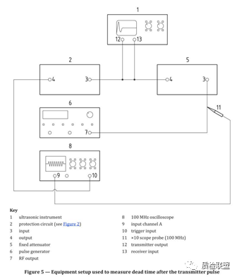
The first type is to measure the dead time after transmitting pulses:
According to the corresponding parts of EN12668.1:2010 and ISO22232-1-2020, the time is obtained, and the general requirement is not more than 10 μ S. The test schematic diagram specified in ISO22232-1-2020 is as follows:
The second type is approximately tested using test blocks:
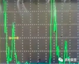
The general principle is to detect reflectors of different depths, find the nearest reflector, and require that the echo of the reflector can be independently recognized from the initial pulse. The closest distance is the blind spot. The distance obtained.
Usually, the CSK-1A test block is used Φ Measure the size of the blind spot by measuring the distance between the circular arc surface of 50 organic glass and the edges of both sides by 5mm and 10mm. If the probe is placed at position I and there is an independent echo, the blind spot is less than or equal to 5mm. If there is no independent echo at point I and an independent echo at point II, the blind spot is between 5-10mm. If there is still no independent echo at point II, the blind spot is greater than 10mm. (The term 'independent' here means that when the echo height exceeds 50% of the full screen, and the valley where the front edge of the echo intersects with the back edge of the initial wave meets the requirement of less than 10% of the full scale.)

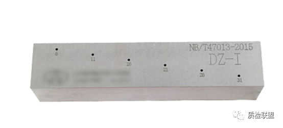
Blind spot testing can also be conducted using the blind spot test block DZ-I. The testing principle is also the same, using the distance of the hole corresponding to the echo of the shortest distance hole that can be independently separated from the initial pulse as the blind spot.