A-scan, B-scan, C-scan for ultrasonic testing
01 About A Scan
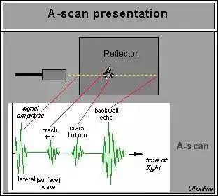
A-scan comes from the English word Amplitude, which means amplitude. The horizontal axis of the display is the propagation time or distance of ultrasonic waves in the tested material, while the vertical axis is the amplitude of ultrasonic reflected waves.
Based on the A-scan defect detection method, when there is a defect in a steel workpiece, the existence of this defect creates an interface between the defect and the steel material, forming a different medium. The acoustic impedance between the interfaces is different. When the emitted ultrasound encounters this interface, it will reflect, and the reflected energy will be received by the probe, A reflected wave waveform will be displayed at a certain position on the display screen at the horizontal axis, which is the depth of the defect in the tested material.
The height and shape of this reflected wave vary with different defects, reflecting the nature of the defects.
The A-scan judgment method for defects is shown in Figure 1.
02 About B-scan
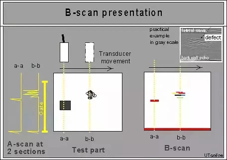
B-scan comes from the English word 'brightness', which means brightness. The scanned image is displayed in a two-dimensional image, and the screen displays a profile parallel to the direction of sound propagation and perpendicular to the measurement surface of the workpiece.
The brightness information is determined by calculating the strength of the reflected ultrasound.
The B-scan display mode is shown in Figure 2.
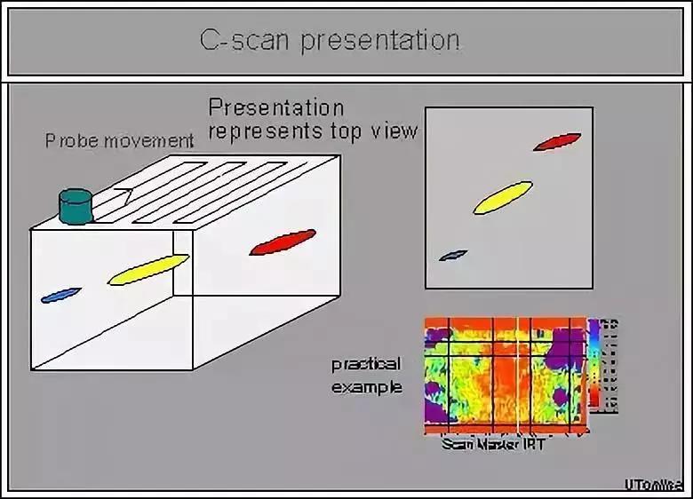
C-scan is derived from the English constant depth, which means to scan a cross-section at a certain depth. It is a signal imaging of moving within a two-dimensional plane and selecting points at a specific depth for A-scan, displaying defect information on a horizontal cross-section.
The C-scan display mode is shown in Figure 3.
The A-scan display mode, in which the horizontal axis of the display is the propagation time or distance of ultrasonic waves in the tested material, and the vertical axis is the amplitude of ultrasonic reflected waves.
There is a defect in a steel workpiece, which forms an interface between the defect and the steel material. The acoustic impedance between the interfaces is different. When the emitted ultrasound encounters this interface, it will reflect, and the reflected energy will be received by the probe. A waveform of the reflected wave will be displayed at a certain position on the horizontal axis of the display screen, The position of the horizontal axis is the depth of the defect in the tested material.
The height and shape of this reflected wave vary with different defects, reflecting the nature of the defects.
The B-scan method displays the scanned image as a two-dimensional image, and the screen displays a profile parallel to the direction of sound propagation and perpendicular to the measurement surface of the workpiece.
C-scan is a three-dimensional imaging scan, and the scanning result is the cross-sectional area of the workpiece.